One very important component of any wireless solution is a real time wireless RF plan.
A real time wireless RF plan shows RF coverage throughout a facility or campus through the use of a heat map. An RF plan tool is also used before deploying wireless to map out optimal locations for the access points based on several factors (We will touch on these factors in a later blog article).
However, to implement a properly implemented RF Plan you need to consider and provide two important components:
- Floor Plans
- Components
Floor Plans
The first thing required to implement a proper RF Plan is a floor plan of the facility or a map of the campus. Preferably the floor plan or map will be in a CAD architectural format or JPEG file. These files can be natively imported into the RF Plan tool while other files such as PDF or TIFF need to be converted to work. Conversions of these files to something that can be imported into the tool can be tricky and risks altering the scale of the floor plan or map.
The scale of the plan or map is critical in that it correctly or incorrectly represents the length and width of an image. If the map or plan is not to scale the RF signatures will not be correctly represented and distances to devices also will not be accurately reflected. This will result in miscalculations of distances between AP’s and devices and can lead to other inaccuracies.
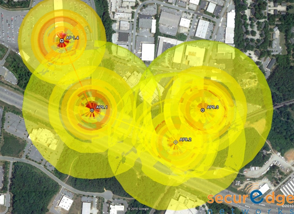
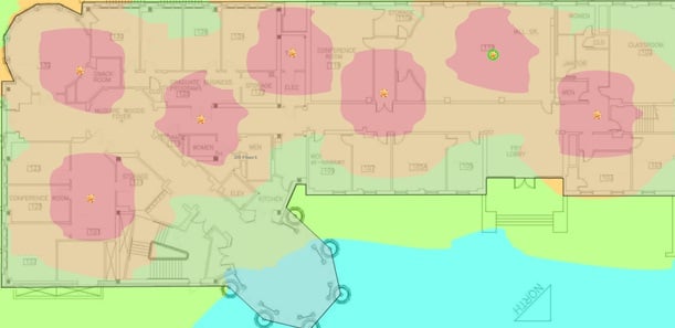
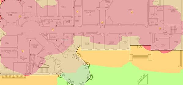
Here is an example of a properly scaled wireless plan done with a CAD drawing that is to scale:
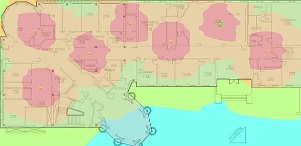
Here is the same design but the scale was done improperly and now instead of the building being 200 feet by 100 feet it is 90 feet by 44 feet. This makes the AP’s think they are actually closer together than they actually are and they will report back much different RF signatures.
Here is an example of an improperly scaled wireless plan done with a CAD drawing::
Dimensions
The second critical component of implementing a proper RF Plan is dimensions. Sometimes we request a building or campus area dimensions, length & width, and are instead given the square footage or acreage. This is not the same as dimensions. A 1,000 square foot building could be 50 feet wide by 20 feet long or it could be 100 feet wide by 10 foot long. Those dimensions are greatly different and RF plans built on them would vary widely in their characteristics and reported locations.
Sometimes dimensions are not immediately available either because no one has documented them or the ability to physically measure the area or facility is not attainable. In that instance we rely on Google Earth’s measurement capability to get length and width of the areas or facilities we are designing an RF plan for.
However, not all areas are well documented yet by Google Earth. I was at a facility recently, a community college, which was not represented well in Google Earth. The image was not clear enough for me to take measurements of the buildings. Luckily, they had a surveyor’s wheel and had a student worker walk the outside dimensions of the buildings to get measurements.
An RF plan is just one step in designing and deploying a really good wireless solution. If you need assistance with this contact us herefor a free wireless network design. We have been designing, deploying and supporting large scale wireless deployments for years and have lots of experience to draw upon.
For starters, check out our Wireless Design Kit below, which is a free download. Best of luck.