Sometimes, in the WiFi world, we are tasked with the unenviable job of designing wireless in less than ideal conditions. Now, most environments we deal with have their less than ideal components, but they are surmountable for the most part.
However, in some cases, you have to make do with what you are given and engineer the best possible solution for that given situation. In other words, “make lemonade from lemons.”
This adage perfectly summarizes a MDU WiFi project I was involved in, where a less than ideal environment was presented to me to design.
In this article, you will learn how to get the most from your MDU WiFi network by analyzing the challenges, design methodologies, implementation process, and results from deploying WiFi at an apartment complex with over 150+ units.
The Challenge
The goal of the design was to make the WiFi work as best I could, given that there was nothing I could do about the number or placement of access points.
While this was unquestionably going to be a challenge, it was refreshing because I knew some of the responsibility of this project was off my shoulders.
I was not responsible for where the APs were going or how many of them were going to be deployed. Those decisions were out of my hands, and all I had to do was to make it work better.
Challenge accepted.
The need for this wireless design was driven by an apartment complex developer and a local cable provider’s intention to provide a high performance wired and wireless network for each resident of a new apartment complex.
In a typical apartment or MDU (multiple dwelling unit) complex, all residents subscribe to some service and either use that service provider’s internet gateway unit or they go out and purchase their own from Best Buy, Staples, Walmart, etc.…
The problem with this is that none of these units are designed to work well with neighboring units, and the central coordination of these units is not possible.
WiFi is a complex medium to work with, but you add in a lack of knowledge in how to properly configure it by installers and the general public, and you have close to the worst-case possible.
In this situation, however, the developer and cable provider wanted to make their implementation work the best that it could and provide a high performing, managed network service for their residents.
Each resident would still have a private network for their apartment, but it would be managed and coordinated to work as optimally as possible.
The environment I was given to design was an apartment complex with 163 units.
Each apartment unit would house a WiFi access point built into a residential internet gateway similar to what your ISP might give you when you subscribe to their service.
The residential gateway unit was installed in a polycarbonate low voltage structured wiring enclosure and connected to a GPON network using fiber optic cabling to the apartment.
The residential gateway unit provided a 4 port Gigabit Ethernet switch, router, firewall, and an 802.11ac 3x3 MIMO access point.
The gateway unit was not an off the shelf unit that could be bought at a store but had some higher-level features that allowed it to be managed along with others in the complex on the cable providers network.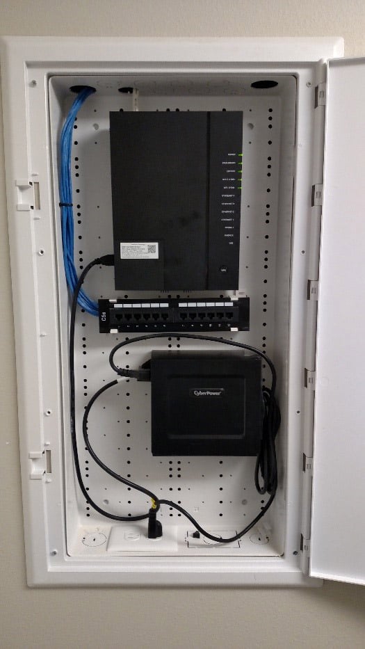
The cable provider would be offering Internet service to the apartment unit capable of up to 100Mbps up and down, so the gateway unit would have to be better performing than a consumer-grade, store-bought unit to support this speed wirelessly.
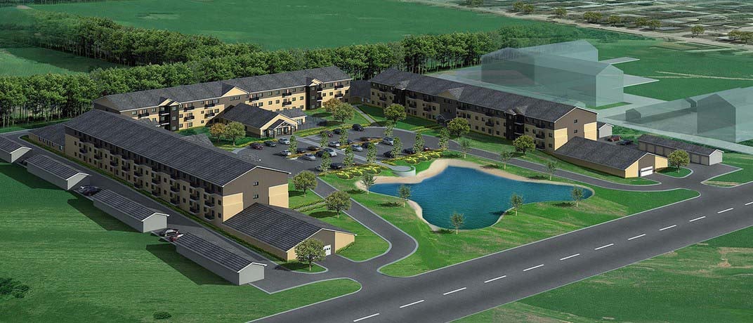
The apartment complex (see rendering above) is broken up into three separate sections, with each section consisting of three floors.
Each section consists of 51 apartments that are connected only at the corners on the first floor.
The apartments ranged in size (800 - 1400 sq.ft.) and were constructed using typical wood stud and drywall construction. The walls between units were double drywall each side, and internal apartment walls were single drywall construction.
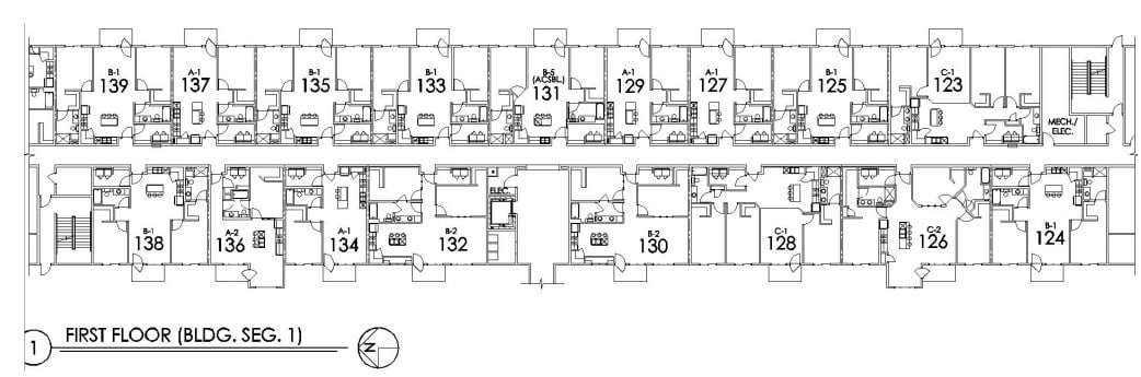
If this complex was a College or University dormitory, I might design an AP every six or seven apartment units. Unfortunately, because this was a residential apartment complex and residents would require their own individual networks, this meant an access point per apartment.
From a WiFi engineering standpoint, I would have six to seven times the RF than was actually needed. This extra RF meant a plethora of issues that I would have to work around to “tune” the networks as best I could.
Our Design Methodology for Better MDU WiFi
In part one of this article, I explained the need for a designed solution to a “worst-case” scenario wireless environment.
The worst-case was an apartment complex where every resident would have their own high-performance wireless access point, and the wireless networks would be overlapping each other everywhere.
The challenge was to make it work as well as possible so that the owner of the complex and the cable Internet provider could sell it as a managed service.
As a result of each apartment having its own wireless access point, there were multiple overlapping RF cells.
With this much overlapping RF, I knew I would certainly see co-channel interference or contention (channels being reused within the same space, which is a WiFi no no) in the 2.4 GHz channel space.
I knew I would probably run into adjacent channel interference or contention (very close neighboring channels adjacent to each other, which is another WiFi no no) in the 5GHz spectrum.
To address this, I recommended the following in the design:
- Each residential gateway unit would require a static channel assigned to each radio; 2.4GHz and 5GHz.
- All auto radio management on the gateway units would need to be turned off completely.
- The lowest data rates for both 2.4GHz and 5GHz radios would need to be removed. This would mean disabling data rates of less than 12Mbps on the 2.4 & 5GHz radios.
- The default power level assignment for each radio would need to be at its lowest possible.
- Channel widths for the radios would need to be 20MHz for 2.4GHz and 20MHz for 5GHz.
The project started off with a predictive design using a site survey and planning software.
Access points were placed in the software application with respect to the locations where the service provider had located the low voltage enclosure that would house the gateway units within each apartment.
(Remember that I had no say in how many access points there would be or where they would be located) Channel assignments were allocated using an auto channel planning function of the software and then doing some spot-checking.
The spot checking was done to make sure I did not have any overlapping channels from units above or adjacent to any of the apartments.
Static channel plans are not something I am used to doing as most Enterprise-class WLAN equipment has automated RF adjustment features that take care of assigning channels and power levels.
In this environment, however, I am not sure that automated RF features would have been of any help. As arduous as the planning of static channels in both spectrums is, it was definitely necessary to make this the best-coordinated effort I could.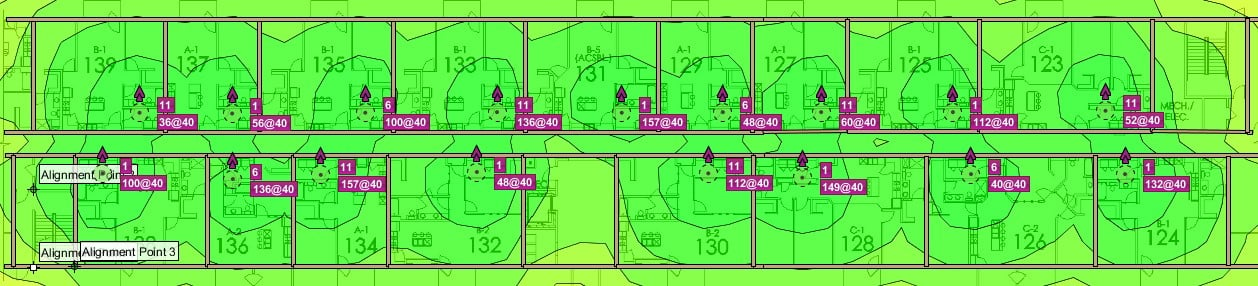
Once I had tweaked the design and adjusted it as much as possible, it was then presented to the customer.
We had a conference call to discuss the items I felt needed to be addressed, and any of the customer’s concerns and questions were answered.
From this call, the next steps in the process were laid out. The customer would be taking the design on-site to implement my recommendations, and we would set a time for a site visit to validate the implementation.
The Implementation Process and Results
In all projects, there comes a time when the rubber must meet the road. This usually happens when the proposed solution must be implemented, and your WiFi design work will be scrutinized.
However, as I pointed out before, most of the responsibility was off my shoulders for this particular design. However, I was still anxious to see if my assumptions based on my experiences and understanding of RF would hold true.
In part 2 of this article, I provided the wireless network design, proposed it to the customer, and discussed the methodology and reasons for why I had done what I had done.
Once they were comfortable with my reasoning and understood the recommendations, they proceeded with the next phase, the implementation of said design.
The customer took the design I had provided them and deployed the gateways to the apartments and assigned the settings as I had recommended.
After the main building was fully deployed with the residential gateway units and were all operational, I scheduled a visit to go on-site and verify the configuration and how it actually performed.
The results we experienced on-site were very enlightening.
After arriving on-site, I began the verification process by using several RF analysis tools that would show me at a glance how the channel allocations looked.
Thanks to MetaGeeks InSSIDer and Eye PA, I was able to confirm that 2.4GHz channels were reused too many times as several of the 5GHz channels were.
These captures above are just from the 2.4GHz channel space, and as shown there were anywhere from 5-7 gateway units all using the same channel.
The 5GHz channel space showed a little less channel reuse, but I still had instances where a 40MHz bonded channel pair was reused up to 4x.
To address how much coverage was actually being experienced from one access point, I loaded a site survey tool on my laptop.
I then walked several adjacent apartment units neighboring apartment 209, which housed the one access point I was measuring.
This survey allowed me to visualize how far the 2.4 and 5GHz radios from one apartment unit would cover.
Below is the output of that survey, which provides an example of exactly how much one access points’ 2.4 GHz radio, even at its lowest power setting, covered the complex floor.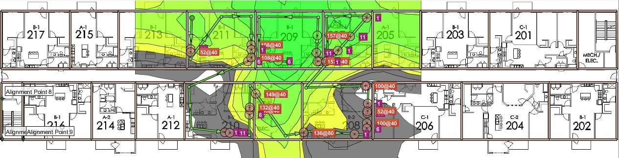
From just this survey sample of a few adjacent units, I could extrapolate from the output that the 2.4GHz radio would cover all the way to the end units 201 & 217.
The across-the-hall coverage wasn’t as severe, but I theorized it was due to the elevator bank and mechanicals directly across from apartment 209.
The floors above and below I could also guesstimate as having almost half of that coverage. For this implementation to work, I had to find a way to reduce this coverage more effectively.
In the implementation of my design, the customer had followed almost all of my recommendations with one exception. They had not removed the lower data rates for the 2.4 and 5GHz radios.
After some review and discussion, they agreed with my recommendation and removed support for 802.11b from the gateway unit radios, which effectively removed data rates lower than 12Mbps for the 2.4GHz space.
Once this was done, I reran the survey and walked the entire floor to re-measure.
Here is what the survey looked like afterward.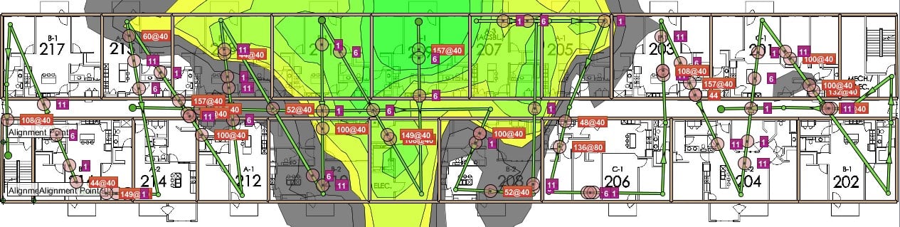
The survey results revealed that the removal of support for 802.11b had minimized the 2.4GHz coverage on the floor quite a bit.
In this environment, anything that we could do to minimize the cell overlap and channel reuse were necessary to improve WiFi performance.
Now that I felt we had done everything we could to “tune” the 2.4GHz spectrum, I turned my attention to the 5GHz space.
As per my recommendations, the customer had set the 5GHz radios to 10% power and had set static channels on the access point radios following the channel plan we provided.
However, they could not remove the lowest 5GHz data rates in their software and were using 40MHz bonded channels.
This was now producing some issues where we saw three to four other neighboring gateway units inhabiting the same bonded channel pairs.
After some additional review and discussion, they decided to test my recommendation that 20MHz channels would be the best use in this environment.
We decided to test throughput to one AP with one 2x2 MIMO client on channel 60+. Using just a simple speed test, we performed the speed test and maxed out the connection at around 96Mbps.
We then had someone go to the floor above and over one apartment unit, using the same bonded channel pair. We both performed a speed test at the same time and saw our results cut almost in half to about 60Mbps each.
The test results confirmed that contention for airtime would trump having faster data rate connection speeds.
The decision was made to move to 20MHz channels, and the changes were pushed out to all the residential gateway units.
With these changes now in place, I reran some of the analysis software again to look at the new channel assignments, which you can see below.
Keep in mind when reviewing the information below, there appears to be some overlapping of channels from the units. However, I took these captures from a second-floor apartment unit, which put me midway between some of these overlapping channels.
When I went to one or the other apartment units showing the use of these channels, I could not detect or “see” the other network using that channel.
In the instances that I was able to see the other network using this channel, the difference in signal (> -25dB) was enough of a separation between the two that they were not in contention with each other.
The screenshot below is to show the layout of the networks and some of the channel allocations. In hindsight now that I am writing this article, I wish I had taken better screenshots from readings in different areas of the complex.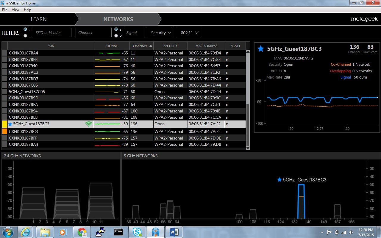
After we moved to 20MHz, I saw little to no overlap, and in some areas, the 5GHz looked very clean with no channel reuse and nicely spaced channel assignments.
After this project, I reviewed with the customer what we had done and how going forward with other similar projects, some of the best practices we had arrived at could be used for them as well.
Here are some of those best practices I feel would be applicable across similar projects:
- Access point power levels have to be turned way down. Typically the lowest setting possible for both radios is more than enough to cover an 800-1400sq foot apartment.
- Static channel assignments are an absolute must. Relying on automated RF adjustment functions will only result in the continual channel and power changes that are disruptive to wireless performance.
- In such a high-density WiFi deployment, only 20MHz channels are suggested. Bonding 20MHz channels together for 40MHz channel space in 5GHz still does not afford enough channel separation.
- DFS channels should be used if the area permits. On this design, we did use DFS channels except for a handful, which the customer requested to be removed. With the addition of the six that they removed our 5GHz channel spacing would have been even better.
- The lowest data rates absolutely have to be removed. At a minimum 802.11b support needs to be removed, and if possible, I would remove everything up to 24Mbps for both radios; 2.4 & 5GHz.
In the course of reviewing the project, some of the possibilities that were discussed for this or future projects by the manufacturer and the Internet service provider are these:
- Disabling 2.4 GHz by default was considered as an option. With 2.4GHz off by default, the spectrum would be cleaner with less contention. If and only if a resident needed it, they could ask for it, and it would be turned on. In this manner, the precious 2.4 GHz spectrum would only be used if absolutely necessary. Most new WiFi-capable devices have dual-band capabilities within the last 2-3 years, so the need for 2.4GHz (802.11b/g) is shrinking rapidly. Some even call it a dead spectrum to never be used again.
- The manufacturer of the gateway unit also discussed bringing in a model of theirs with identical specs except for a less “powerful” WiFi chipset. They felt that this would trim back the RF cell overlap and provide a better performing unit in such a dense deployment.
Final Thoughts
As atypical as this deployment was, I hope that this article sheds some light on how this sort of “worst-case” scenario can be done successfully.
However, it takes a service provider and manufacturing partner who agrees on performance as paramount and willing to expend the resources to make it happen.
It was a project I was glad to have participated in and makes me hopeful that other such implementations can be done this way.
If you're currently planning an MDU WiFi deployment and have questions, please contact us here, our engineering team is ready to help.
This blog post was originally written in August of 2015 but has been revamped for accuracy and thoroughness.